compDuctor
Fredy Monterroza (fredym@seas)
Ye Yang (yangye@seas)
Jing Qiu (qiujin@seas)
Introduction: The goal of the project was to build a machine that could play the piano. We wanted to make the system compatible with any keyboard of similar dimensions so that all a user would have to do is slip the piano into place and the machine would play some tune. The major goals of the project were to build as low cost a system as possible, which in turn meant to use as few motors as possible and build a structure that mimics a hand (more closely, a finger) and to provide an interactive experience for the user. Following is a description of the hardware, mechanical structure and software used in building compDuctor.
Below is a photograph of the finalized product, which will hopefully be on display in the second floor of Moore near the ESE office (sans Nexus 7 Tablet). 
compDuctor
User Interface:
One of the key features of compDuctor is the real-time user interface for interacting with the system. The interaction takes place when the whole system is powered on (AC-DC Adaptor plug-in) and the Android device that has our app installed is paired with bluetooth module. Notice the name of our bluetooth module is “Fire-fly 5E5C”. After the powering and the pairing procedure, the user is allowed to choose two mode of the compDuctor system: the default mode or the streaming mode. By choosing the default mode on the Android device, the compDuctor system will be able to perform songs that are already in the system’s playlist. Then, the user can interact with the system using the keypad showed on the picture above. In this section, the usage of the keypad will be discussed. The streaming mode will be discussed in detail later in the bluetooth and Android App sections.
Firstly, we decide to utilize the four keys at the top of the keypad, which are “1”, “2”, “3”, “A”. They will be programed to the function of “Pause”, “Start/Resume”, “Stop”, and “Next”. If the user press the “Pause” button, the compDuctor stops playing, and the servos and solenoid will be freezed to the current position. The user can continue the performance from where it left off when pressing “Start/Resume” again. Whenever “Stop” button is pressed, the compDuctor stops the current task (whether it’s right in the middle of a performance or it’s receiving songs from the Android App). And if the “Stop” button is pressed during the performance, the system stops and pressing “Start” again will not resume the music, the system will start playing the same music from the beginning.
The Pin out of the keypad is shown below.
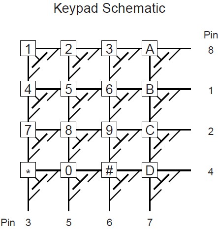
Keypad Pinout
We are only using the top four buttons to trigger interrupts for the mbed to handle. Thus, Pin 8 will be powered 5V and Pin 3, 5, 6, 7 will be grounded with 1k resistors. The EAGLE schematics for the keypad circuit is shown below.

Keypad Circuit Schematic
The MBED_DIGITALIN_1, 2, 3, 4 will be connected to the mbed’s p5, p6, p7, p8 for hardware interrupts detection. Pressing any button from the top four will give the corresponding mbed pin a rising edge from 0V to 5V.
Bluetooth:
In this section, we will introduce the usage of the bluetooth module: BlueSMiRF Gold from Sparksfun. Firstly, on the bluetooth modem side, the wiring example is shown below:
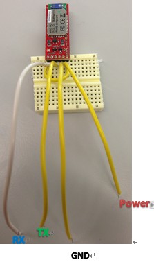
BlueSMiRF Wiring Example
The pin CTS-I and RTS-O is connected to each other, the VCC pin is powered by 3 - 5V and GND is connected to the common ground of the system. TX and RX will be connected to the corresponding RX TX input on the mbed.
On the other hand, the microcontroller side needs to set up a serial read in. The mbed.h library has a virtual serial class that can turn any pin from port1 into TX and RX serial port. For the sake of this project, we will use p9 as TX and p10 as RX. By creating a Serial type object with the assigned pin p9 and p10, the mbed is able to communicate with the BlueSMiRF Gold as a serial communication.
Notice that the Baud rate of the serial communication between the BlueSMiRF Gold and the mbed should be 115200 (Default). We can change the baud rate by entering the command mode of the BlueSMiRF. The range of the baud rate can be 9600, 57600, and 115200.
Android App: The android app is aimed to provide an interface for users between the system and the music library. Users can download the music from Internet and stream the tracks into the compDuctor. The android app communicates with the system via the blue tooth module on tablet and the BlueSMiRF.
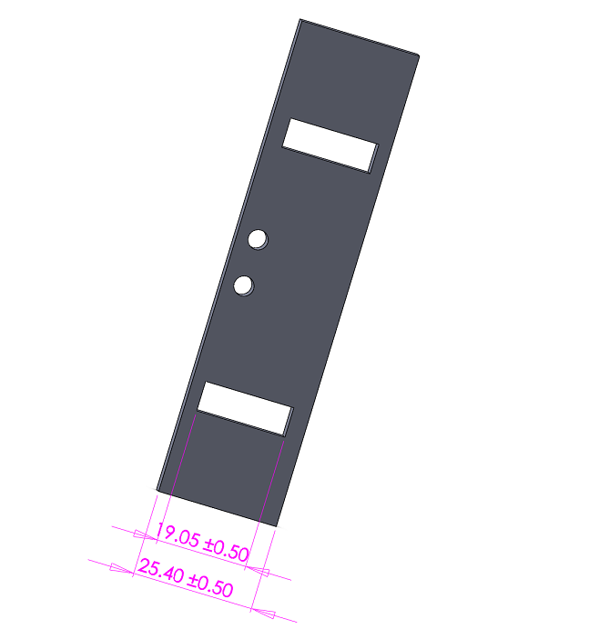
Mechanical: The machanical structure was modeled in SolidWorks and appropriate DWG files were created for the purpose of laser cutting the necessary components. compDuctor required three finger structures to span all keys except for the leftmost and rightmost two. Each finger had a range of 6 white keys and covered about 10 keys over that range. The left finger covered keys from Sol to Mi at the lowest octave, the middle finger covered keys Mi# to Re and the right finger covered Re# to Do. Each finger is actuated by a servo and solenoid. The servo was responsible for spanning the reachable space of keys while the solenoid was responsible for mimicing a key press. The servo was held in place by a part labeled ‘holdServo’. This part was mounted on four legs (‘aFontOfBaseSuppor’) each of which had an upper and lower ‘frontTruss’ so as to fix the servo in a rigid position when the solenoid was actuating a finger press and also to prevent the servo from

Hold Servo a Front of Base Support
falling.
The solenoid was mounted against two walls called ‘holdSolenoid’. The dimensions of these were such that the solenoid cleared the base of the structure (‘aBASEofSYSTEM’). A problem encountered with the solenoids was that they exerted a large amount of force that caused the structure to resonate from the vibrations resulting from the solenoid retracting. To remedy this a ‘soundRoom’ was made consisting of 2 walls whose interior was lined with micro-fiber cotton pads. The hope was that these walls would absorb some of the sound produced by the solenoids. A simpler and more useful approach was to add dampers (also cotton pads) to the legs that held the compDuctor base. This way, any shocks were absorbed before they hit the table. Lastly, the finger structure was composed of a ‘finger’, two ‘sides’, an ‘arch’ and a base for the finger structure which was rigidly attached to the servo head. The finger was an extrusion which would extend from the center of the solenoid to about 1.5’’ into the piano. The ‘side’ was used to provide a pivot point for the finger. This pivot point had a rod made from everyday nuts, bolts, spacers, and washers. Of course, the dimensions of the side part were taken such that the rod would allow for just enough freedom so that the finger could pivot. The setup also had a mount for the paino so that it would be raised to just enough height so that the throw of the solenoid was enough to create a keypress, thus producing sound on this keyboard.
I would like to note that rather precise measurements had to be taken to ensure that as few design iterations were machined. In any case, several finger structures were iterated over. The first was the most most intuitive and somewhat naive approach. This structure had a pivot point supported by a leg that would fall out of place if the finger landed in a slightly different spot than it started from. The leg was supposed to move along with the finger, and the friction at the point of contact between the pivot support and base would cause additional problems. The major problem was that this structure had too many moving parts. So, in order to simplify the structure, we tried to use a smaller solenoid that was directly mounted on the tip of the finger so that no pivot point was needed and only servo actuation to reach the key. Since non of us are very mechanically inclined, it took a lot of head bumping and failures to finally realize that an arch and attaching a pivot point directly on the servo would satisfy our needs.
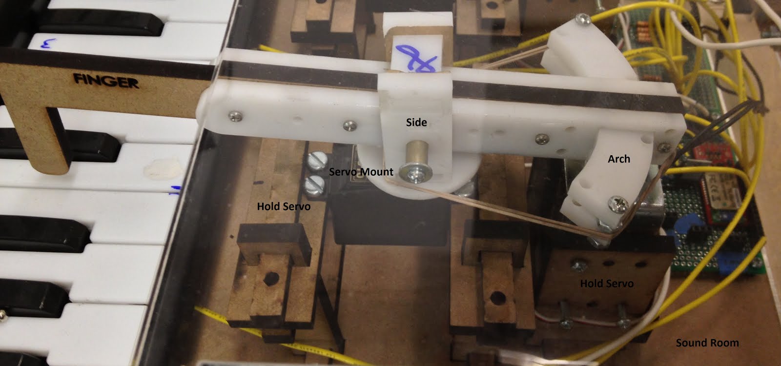
Close-up of Actual Finger Structure and Solenoid
Software: The software allowed for the streaming of music via an Android App which would maintain the library of music on the mbed and update it via bluetooth. compDuctor also has a jukebox functionality operated through the keypad (and arcade buttons on the ESE Office Display). The control flow of the music playing mode was done through 4 functions described in the Music section below.
Calibration: Each finger had its own set of PWM values associated with a certain key. The duty cycle was directly mapped to a key and each time the structure was changed, or a different servo was used, the system had to be re-calibrated. This is done with the function calibrateHand(). Pressing ‘w’ and ‘d’ increased and decreased the PWM value respectively. Pressing ‘x’ saved the value.
Music: Currently, a piece of music is translated into our format by hand. The music for our system is broken up according to left, middle, and right finger. This means that any keys in the range of the left, middle and right fingers are assigned to be played by that same finger. The format of our music is {Key, Time to Next Key, and Press Duration}. So, each finger has an array that is read by the set of functions:
setServos();
pressKey();
depressKey();
setNextKey();
Set servo reads the “Key” element and assigns the PWM value of the corresponding finger. pressKey() will set the GPIO pin corresponding to the solenoid of the same finger for which this Key has been mapped. This will only happen if 200ms has passed. This value represents the time it takes for the servo to traverse the maximum range of keys. The lower bound on this value was about a tenth of a second. So, if the value was set to less than this, the servo would not clear the set of black keys. This limit inherently places a limit on the speed of the music we can play. For example, a piece like fur-elise would be difficult to actuate with a single finger. depressKey() checks if the currentTime - pressTime has exceeded the pressDuration element of the tripple corresponding to this key. Lastly, setNextKey() will increase the index (i+3) to point to the next key for this finger if the timeToNextKey has been exceeded. Note that all of these functions make use of a global timer defined by Timer tim; and each read the current time according to currentTime = tim.read_ms();
Circuit Design:
The compDuctor project features three major circuit sub-system, which are the Driver, Power Supply, and Bluetooth Peripherals. They will be discussed in detail later on in this section. Below is an overall circuits arrangement of the compDuctor system (without the power supply sub-system)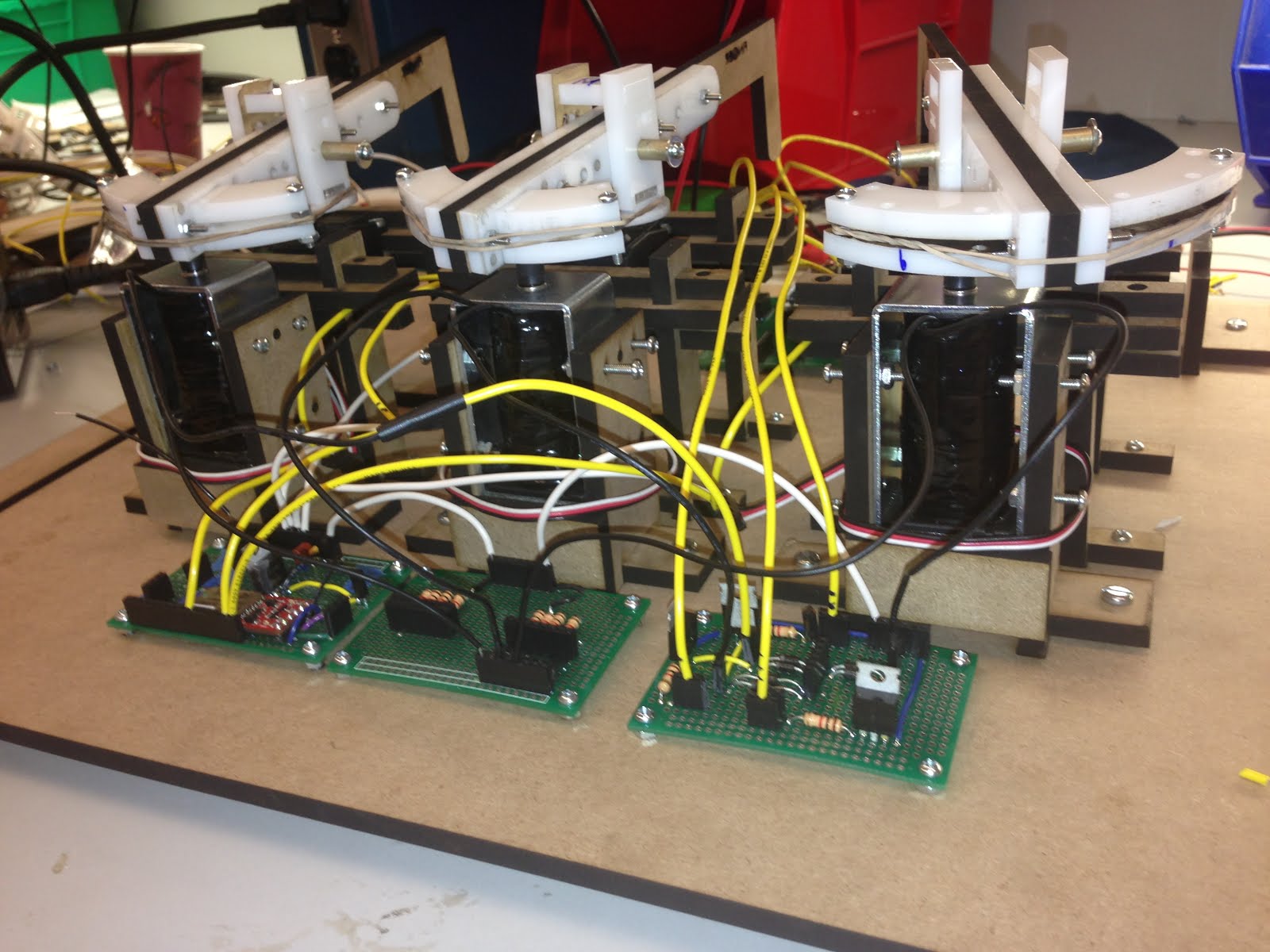 Overall Circuits Teardown of the compDuctor (Front View)
Overall Circuits Teardown of the compDuctor (Front View)
Overall Circuits Teardown of the compDuctor (Side View)
1.Driver Circuit
There are two types of driver circuit in this project. One is for driving the 36V solenoid, the other one is for driving 5V LED. Both circuits are using mbed’s GPIO output as the control signal. Notice that, even if the GPIO output voltage (3.3V) is bigger than the least positive onset voltage of the diode LED, the current from the GPIO is not enough to drive it, therefore we still need external voltage for the LEDs.
a. Solenoid Driver Circuit
Firstly, the solenoids we are using for this project have a working voltage of 36V and a working current of 0.8A. After examining the datasheet of these solenoid, we decided that 12V is able to provide enough force to hit the piano keys (We noticed that the increasing rate of Force - Voltage decreases gradually, thus voltage lifting beyond 20V has little impact on the force output). However, working at 12V still needs a current of approximately 600mA. The picture below roughly describes our design thinking of our solenoid driver circuit. Using a specific transistor (TIP102), we built the circuit based on the switch feature of the transistor. The diode 1N4004 is for protection.
Solenoid Driver Circuit Design
With the above schematic in mind, we basically triple the above circuit organization and designed our own relay board for the three solenoids. The EAGLE schematics is shown below.

Solenoid Driver Circuit Schematic
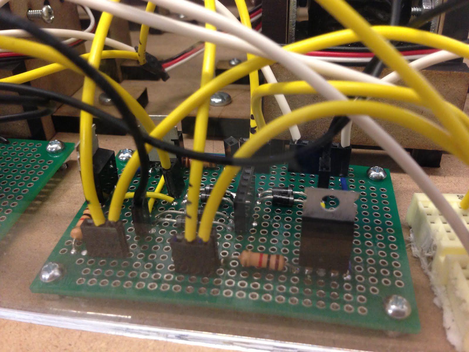
The Actual Solenoid Driver Circuit (Wired)
b. LED Driver Circuit
Firstly, the LEDs that we are using for this project are common cathode RGB LEDs which have working voltages of 3 - 5V and working currents of around 200mA. The Pinout for the LEDs we used is shown below
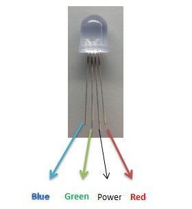
Common Cathode RGB LED Pinout
Introduce power (5V) to the third Pin starts from the left (which is also the longest pin among the four pins). And by choosing to ground one of the color pin, the LED will shine the corresponding color. The other color pins can be floating or powered by 5V. If we ground two of the color pins, say blue and red, we get the combination: purple. Similar to the solenoid driver circuit, we can use transistors such as 2N3904, 2N2222, or TIP102 to act like a switch. The EAGLE schematics is shown below. If the mbed GPIO signal is low (0V), the corresponding color turns on. If the mbed GPIO signal is high (3.3V), the corresponding color turns off. During the examining of those LEDs, we found that the RED pin needs twice the resistance than the BLUE and GREEN pins when connected to ground. So, we chose 100Ω for BLUE and GREEN, 200Ω for RED.
LED Driver Circuit Schematic
The Actual LED Driver Circuit (Wired)
2. Power Supply Circuit
The compDuctor system is using a 12V AC - DC Adaptor as the foundamental power source. The Power Supply Circuit has two basic functions: protection, voltage regulation and distribution. We need two voltages for the entire system. The 12V for the three solenoids, the 5V for the three servos, mbed, LEDs, keypad, and the bluetooth module. The EAGLE schematics for the Power Supply Circuit can be found below.
a. Short Protection

Short Protection Circuit Schematic
b. Voltage Regulator
Voltage Regulator Circuit Schematic
3. Bluetooth Peripherals
We are using SparksFun’s bluetooth smirf GOLD module for the compDuctor system. The peripheral circuits with LEDs are shown below.
Bluetooth Peripheral Circuits
Notice that the blue, yellow, and red wires coming out from the CD4094 is the mbed output for the LEDs. The brown and purple wires are connected to the mbed PIN p9 and p10 as TX and RX. We simply use serial read in for the communication between the BlueSMiRF and the mbed.
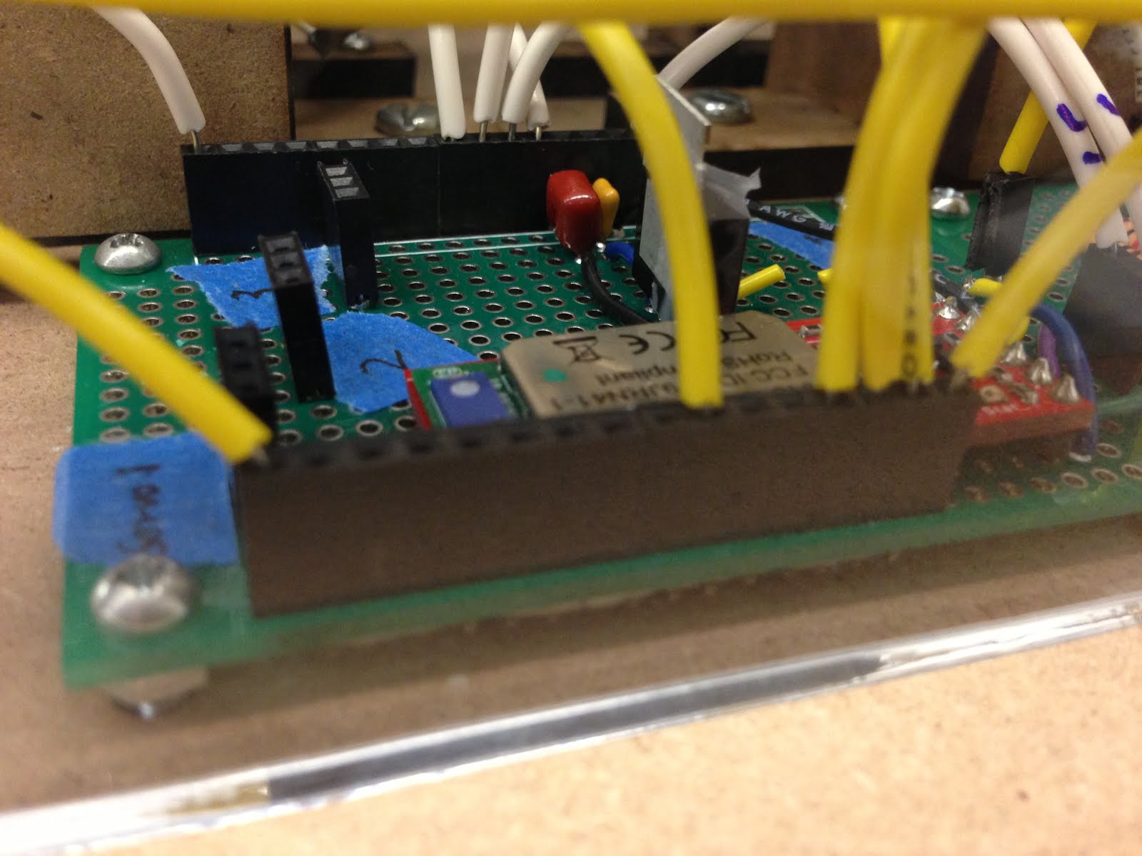
The Actual Bluetooth Peripheral Circuits (Wired)
Links and Reference:


